Andy Doro
Inspirations
I was able to detect changing magnetic fields using a simple pickup from Radioshack which produced sound. But I wanted to create a visual response as well. We are familiar with sound changed into an image using all sorts of sound visualizations in computer music players. I wanted to create something physical. For this reasonb I decided to create a sculpture which reacted to sound.
My original plan involved solenoids in a spheroid shape, such as a dodecahedron. Each solenoid would respond to a certain frequency band, and the whole thing would have a spandex "skin" surface.
Unfortunately, I ordered the wrong sort of solenoids. The type I ordered were far too heavy (3 pounds each) to be used in the way I intended.
I began to despair until someone suggested I use vibrational motors. I decided to use a tensegrity structure which vibrated, since the beams in a tensegrity structure don't touch I thought I could get more vibration.
I ordered some very inexpensive vibrational motors online ($0.50 each). These are the same sort of vibrational motors used in cellphones and pagers.
How Does It Work?
The tensegrity structure is one of the simplest three-dimensional objects. I discovered a bit about tensegrity from the website of Kenneth Snelson, a student of R. Buckminster Fuller.
The computer peforms fast fourier transform on incoming sound from line-in. Therefore it can use virtually any sound source- microphone, MP3, CD player, etc. that can be transmitted along a 1/8" phone jack.
The computer runs Max/MSP in order to detect beats. The Max patch uses an external object called bonk~ which is used for beat detection. bonk~ analyzes the sound signal into eleven frequency bands. The final 10 are averaged to give us six frequency bands. Each corresponds to a motor which is attached to a beam in the tetrahedron. The patch also uses SimpleMessageSystem to send ascii message from Max/MSP to the Arduino through serial communication along a USB cable.
When the threshold number of the frequnecy band is crossed, Max sends information to Arduino to send voltage to the motor. When the frequency band number drops below the threshold, the voltage is turned off.
Materials
electronics
Construction
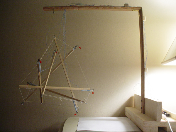
The tetrahedron was created using balsa wood beams. Each was cut to 6 inches and a screw eye was attached to both ends. Elastic bands were used as the tensional elements in the structure.
The wooden base was mostly constructed out of wood from the scrap pile. There is a section for the Arduino and perf board.
The long suspension arm is made of a floor binder purchased at a hardware store. It was cut at a 45 degree angle and joined at a right angle using a corner brace and gorilla glue.
The tetrahedron is attached to the suspension arm with a screw eye and a strand of monofilament.
There is a hole drilled into the suspension arm to allow for wiring to go through. There are three wooden wire guides along the back of the suspension arm, leading down to the perf board.
Wrapping wire was used because it is very thin and light.
The motors each have an LED attached to provide extra off-center weight. Each was soldered to a long double strand of wrapping wire and then inserted into a cut plastic drinking straw. The straws extend past the end of the screw eye so the LED can spin around without hitting anything. The straw is affixed to the wooden beam using scotch tape.
6 digital-out pins of the Arduino each power a motor. The connection is made using a perf board.
Code
Uses bonk~ for beat detection and the SimpleMessageSystem to send messages from Max/MSP to Arduino.
Arduino code
- modified version of the example code for SimpleMessageSystem.
Video
dt1.mpg
MPG, 22.2 MB, 1:04
lucas.mp4
MP4, 4.15 MB, 1:02
Future Plans
Introduction to Physical Computing
Carlyn Maw, ITP, Fall 2006
My initial interest was in doing a project involving some invisible part of the electro-magnetic spectrum, to allow people to "see" or hear "Hertzian space." These investigations were compiled in
magnetophonics.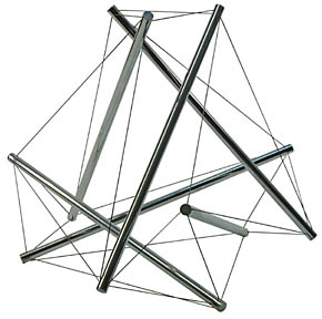
sculptural
software

shot by Andy Doro
shot by Lucas Longo